ArcGIS GeoPlanner allows you to mark spatial relationships in your scenario's layers using a configurable set of criteria. Spatial relationships can be either negative or positive. If the location of one feature negatively affects the location of another, you can mark the intersecting area as a conflict using the project screening tool and adjust your design accordingly. For example, a land use consulting firm may want to report the intersection between a river bank and a proposed new location for a new shopping center. The overlap between these two features would be considered a conflict.
There are a number of spatial relationship options aside from intersection that can be used to define project screening criteria. You can further define your screening criteria to consider layers’ attribute information. The output of a project screening analysis is a new data layer containing features mark during the project screening.
Screening criteria
Conflict screening criteria can be configured in the Project Screening Criteria dialog box. By setting specific criteria, you can accurately mark spatial relationships based around spatial operators and attributes. Building a set of conflict screening criteria is similar to writing an SQL query or a definition query.
Screening criteria consists of a number of items with each item containing, at a minimum, a data layer and a spatial relationship option. There are a number of spatial relationship options available to you:
- intersects—The input design layer intersects with the selected layer.
- does not intersect—The input design layer does not intersect with the chosen layer.
- within a distance of—The input design layer is within a straight line distance of the chosen layer.
- not within a distance of—The input design layer is not within a straight line distance of the chosen layer.
- completely contains—The input design layer is completely surrounding the chosen layer.
- does not completely contain—The input design layer is not completely surrounding the chosen layer.
- completely within—The input design layer is completely inside of the chosen layer.
- not completely within—The input design layer is not completely inside of the chosen layer.
Example 1 - Attribute filters
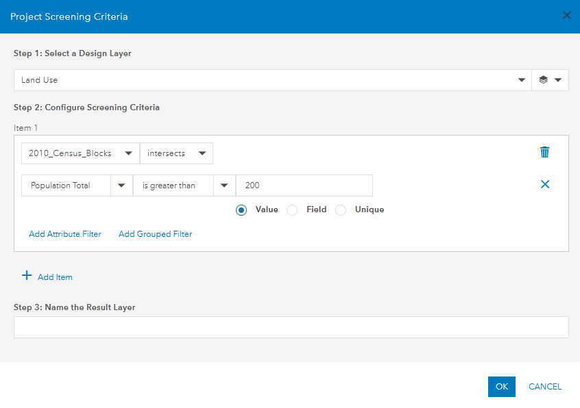
An attribute filter can be added to an item to specify a spatial relationship using a field. For example, you may want to find the intersection of a design layer and census tracts where the population of the intersecting census tracts are greater than 200.

Example 2 - Spatial operators
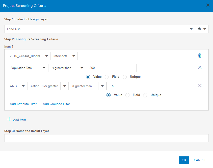
You can connect multiple attribute filters together in an item using a spatial operator such as AND or OR. For example, you may want to find the intersection of a design layer and census tracts where the population of the intersecting census tracts are greater than 200 and where the population over the age of 18 is greater than 150.

Example 3 - Grouped filters
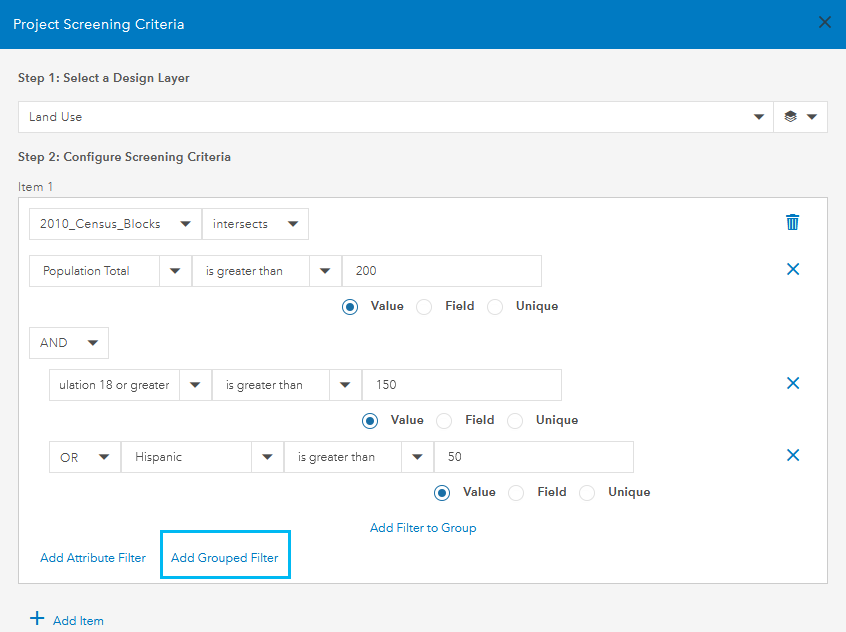
A grouped filter is a set of two or more attribute filters where the result of the grouped filter is used with a spatial operator. For example, you may want to find the intersection of a design layer and census tracts where the population of the intersecting census tracts are greater than 200 and where the population over the age of 18 is greater 150 or the number of Hispanic residents is greater than 50. In this case, if either the population over the age of 18 is greater than 150 or there are greater than 50 Hispanic residents in an area, a spatial relationship is marked.

You can add additional items to your project screening criteria. Similar to how attribute filters can be joined with a spatial operator (AND or OR), you can join items together as well.
Note:
Items are processed in sequence. The output of the first item is used when processing the second item, and so on for the number of items in your criteria.
Run a project screening job
You can run a project screening job from GeoPlanneragainst features in your scenario to mark spatial relationships.
- Open a project in GeoPlanner.
- Click the Evaluate tab.
- Click Project Screening.
The Project Screening dialog box appears.
- Click Configure Screening Criteria.
The Project Screening Criteria dialog box appears.
- Choose a design layer to screen underlying data layers.
- Optionally, filter the design layer you selected by clicking Feature Type Filter button
 .
. - Configure screening criteria for items that will be used to mark spatial relationships against the design layer.
Each item contains, at a minimum, a data layer and a spatial relationship option. You can use an attribute filter to indicate features in a data layer that meet specific criteria. You can add a grouped filter containing multiple attribute filters. Attribute filters can be joined with an AND or OR operator.
Tip:
- Items are processed in sequence. The output of the first item is used when processing the second item, and so on for the number of items in your criteria.
- You can remove an attribute or group filter from an item by clicking the Remove
 button next to the attribute or group filter you want to delete.
 - You can remove an item by clicking the Remove Item
 button next to the item you want to remove.
- Type a name for the output data layer.
- Click OK.
The Project Screening Criteria dialog box closes, and an outline of your criteria appears on the Project Screening dialog box.
- Click RUN.
The project screening job runs against your criteria and a new layer appears in the table of contents.
Understanding project screening output
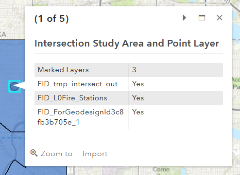
Understanding the output of a project screening job is critical when making decisions with your data. You can visually see spatial relationships between your data on the map by viewing the output layer from your project screening job. For additional information, you can select a feature on the map to see the number of marked layers as well as the layers that have been marked with a spatial relationship. In the following image, there is a feature with three marked layers, and the list of layers that were marked.

The output layer from a project screening job where the criteria is joined with an AND spatial operator is the feature type of the smallest input layer. For example, joining a polygon, a line, and a point layer with an AND spatial operator results in a point layer as the output. The output of a project screening job where the criteria is joined with an OR spatial operator is the same feature type as the input layers.
Note:
Using input layers that do not share the same feature type when using an OR spatial operator is not supported.